Grotto 2: Retro
This
page designed to operate under Netscape Navigator(TM) Version 3.0
Last update 02JUN2019
If you’re a dedicated RC antique collector, do not look at the following! These are the results of hot-rodding old RC equipment to be legal and flyable. What’s the point of keeping RC history at home in a glass case when you could be out at the flying field enjoying it with your friends?
This
is an anodized Futaba F7xx that was given to me by
Mike D’Amico new-in-box. This type was similar to the F710, but the PC
board is
definitely different. You’d never know it was a Futaba except for the
PC board
and some very small lettering inside the meter.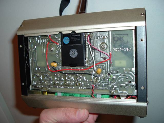
I left the encoder stock but did replace it’s polystyrene capacitors. The transmit chain and oscillator were removed except for a modulator transistor that I needed as an inverter. Originally I was using an FMA transmit module, but it went for a Burton, fortunately while the plane was on the ground. RF power is now provided by a 50 MHz Futaba TK module, but this required that I slice a rather large hole in the PC board. Oh, well! At least it’s 100% Futaba.
This Tx looks and flys great!
One thing interesting about this system was that the entire charger was built into the transmitter, including a transformer. The transformer is important to those of us that may grab a system being charged while in bare feet on terrazzo. Some transmitters from the “anodized” and “vinyl” eras didn’t isolate the charger power line from the case. Yikes!
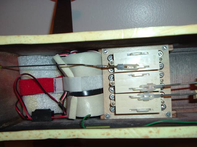
This is a picture inside the radio compartment of my Dave Platt Executor that I’ve been using to fly the above radio. The servos are Futaba FPS2’s. That’s not a typo, it really is Futaba Proportional Servo type Two. Dual linear outputs, reasonably quick and strong. The amps were replaced with some from Futaba S148’s to be compatable with modern receivers. If you decide to duplicate this, you will also need a 47K damping resistor in series with the arm of the feedback pot to settle the jitters.
Back in the late 60’s when these radios first started appearing, Kraft was king and Futaba’s reputation wasn’t very good. Rumors circulated that modelers were crashing due to poor output power and antenna dead spots. I remember flying these systems with no problems, though. Futaba even put out magazine ads touting their technical expertise to counter the rumors. Even today, though, if you look at the guts of these radios the quality is evident. With their low street cost, the Japanese would ultimately break the American RC market.
You should be able to find one of these on ebay for $50 to $100 if you want to duplicate this conversion.
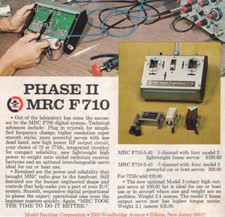 MRC-Futaba
advert
MRC-Futaba
advert
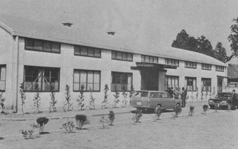 Futaba
factory 1970
Futaba
factory 1970
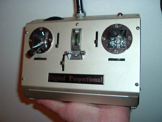
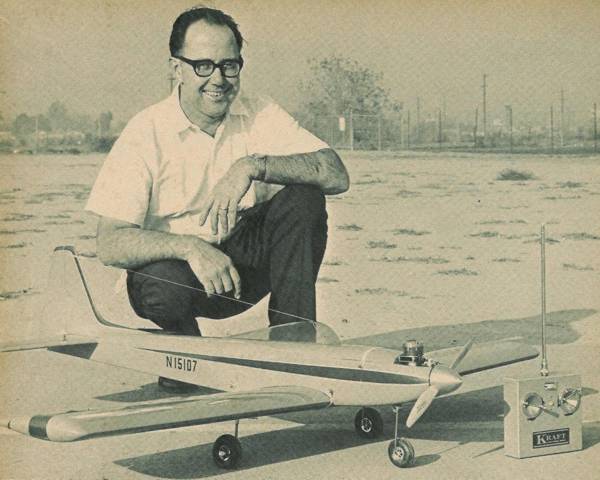
Let’s
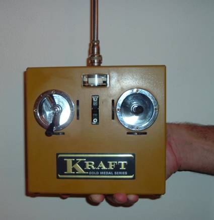
not shortchange Kraft! Here is a beautiful ’68
vintage vinyl Gold Metal transmitter like I had in the early ‘70s. Of
note is
the removable antenna with the military-style connector. This is also a
50MHz
Futaba TK module conversion. The oscillator transistor was reused as an
inverter. All other RF chain components were removed, including the
meter
circuit. The meter now acts only as a voltmeter in all of my
conversions, as I
had second harmonic problems once when I left the RF detector
circuit in.
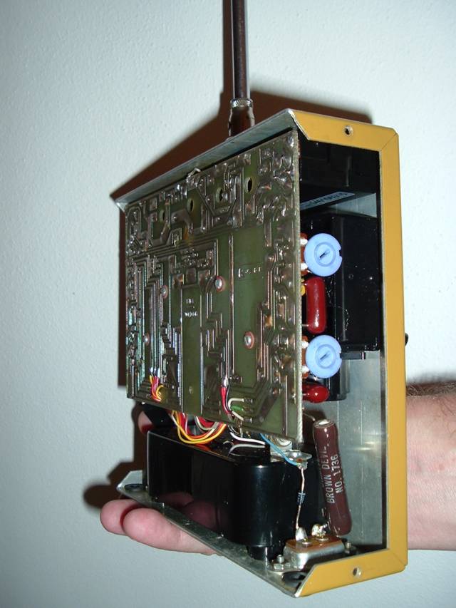
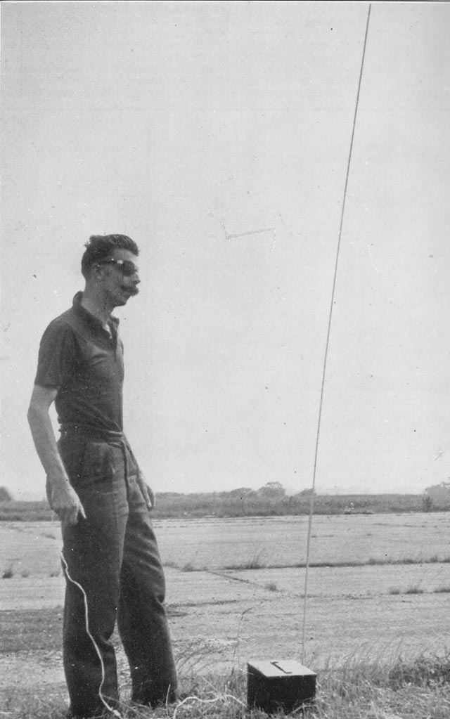
You can see the Futaba module just above the left hand stick assembly. The in-Tx charger (the diode, big brown resistor hanging on the connector and a light bulb mounted on top of the battery case) still works and charges the modern NIMH pack hidden in the black plastic case.
Big, sturdy and simple, this Tx also flys great and attracts comments at the flying field. I got this one off ebay with good working KPS-9a servos for less than $50.
Here's an update! This is the same old '68 Kraft transmitter, but as you can see the original printed circuit board has been completely removed. The module is similar, in this case a Hitec dial-a-crash, but held in with velcro so it can be easily swapped out. The batteries are no longer nicads and have been replaced with a 1500mAh LIFE battery from Hobby King. It fits nicely in the original Kraft battery magazine. The encoder is completely new and is in first production beta testing as of this date. Please contact me if you would like to order one.
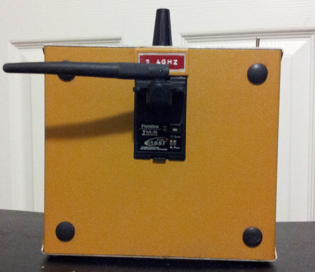
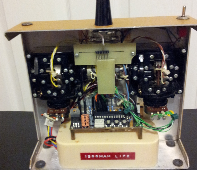
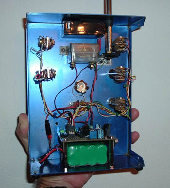
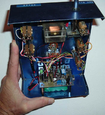
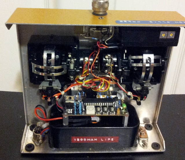
Pictured above is a newer Series Eighty Kraft, again with 1500mAh LIFE batteries and the new encoder. In this case, however, I chose to nibble out the back panel to fit a 2.4gHz TM-8 module. On the inside I used 1/8" fiberglas to make a shelf for the module at just the right height so that the module snaps into the back panel. Note the shelf assembly is held on the top by two screws used in the corners of the stick assemblies. The bottom end of the shelf has a leg (not visible) that rests near the bottom of the Nobel power switch. This leg provides support, but only attaches to the shelf and not the chassis.
Note also that the module contact for the antenna has a white wire connected to the original antenna base. That's just in case I want to snap in a VHF module and use the old long antenna.
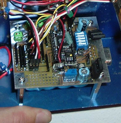
Here's some more information about the encoder:
This encoder was developed for use as a retrofit encoder for vintage transmitters, as an encoder for control-line transmitters, or a basis for robotics transmitters.
Features
· Eight channels, six proportional plus two switched
· Reversing on all channels
· End-point adjustment on all channels
· Direct hardware connection to Futaba style FP-TP style modules including TM-8, Hitec, Corona, etc.
· Center and stick range calibration in-situ. No diddling with stick pots!
· Center alignment to trim to 1.5ms
· Stick pots interface with servo pigtails, allowing easy control order adjustment
· Simple onboard programming, no need to connect to an external PC.
· Dimensions 3" x 1.5"
· Programmed microcontrollers are available separately for integration into custom circuits
Email me if you would like one.
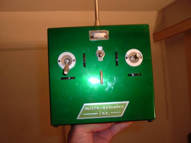
Micro-Avionics was a big name in the middle sixties. Using mostly Orbit
mechanics for their sticks and servos, they were a class act. Look at
this
beautiful anodized green transmitter vintage 1966. They really tried to
minimize and smooth the appearance…strikingly stark by today’s
standards.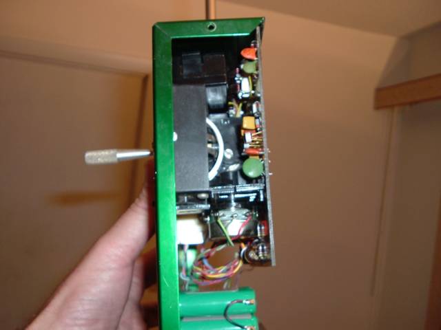
The hot-rodding is the same as the aforementioned Kraft, except that the inverter was not needed at the encoder to RF module interface. Note that this Micro Avionics has a positive ground!!! Despite this, the encoder is built with NPN transistors suspended between the case positive and -9.6V.
I remember seeing local legend Bill Youmans (later known in heli circles) flying this type transmitter in the sixties. He commented to a bystander that he had startup problems with the Tx encoder until all the capacitors were replaced. Likewise I have replaced the encoder capacitors with new monolithic or polystyrene throughout.
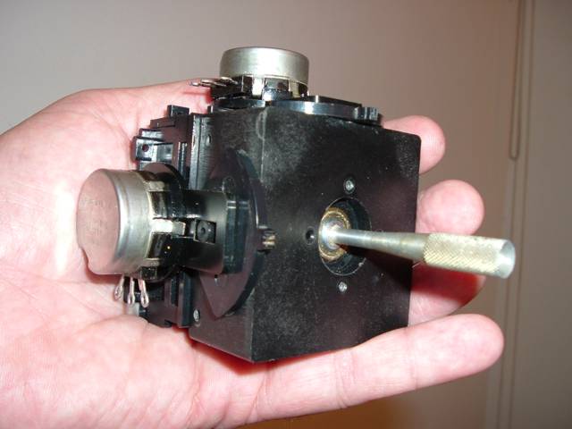
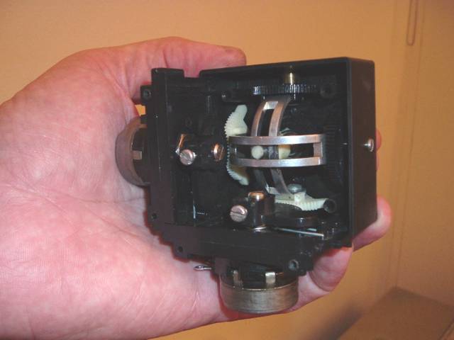
Here’s a couple of pictures of the Orbit stick assembly from the same Micro Avionics transmitter. I had to remove it to replace the pots, which appear to have been replaced at least once before. Obviously, it has seen a lot of use. I don’t know a lot about pots, but elected to replace them with some Clarostat conductive plastic pots (Jameco part#13995CL). This interesting design used gears to reverse the stick direction to match the trims.
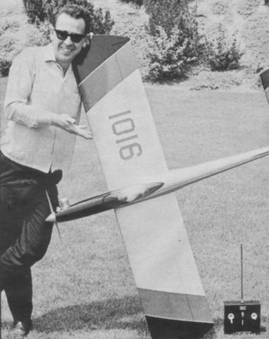 Doug Spreng w/Micro
Avionics guided Thunderstormer
Doug Spreng w/Micro
Avionics guided Thunderstormer
Flight
testing:
Tech
Details:
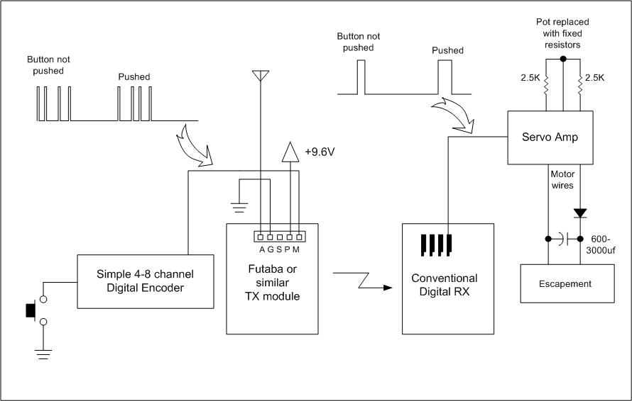
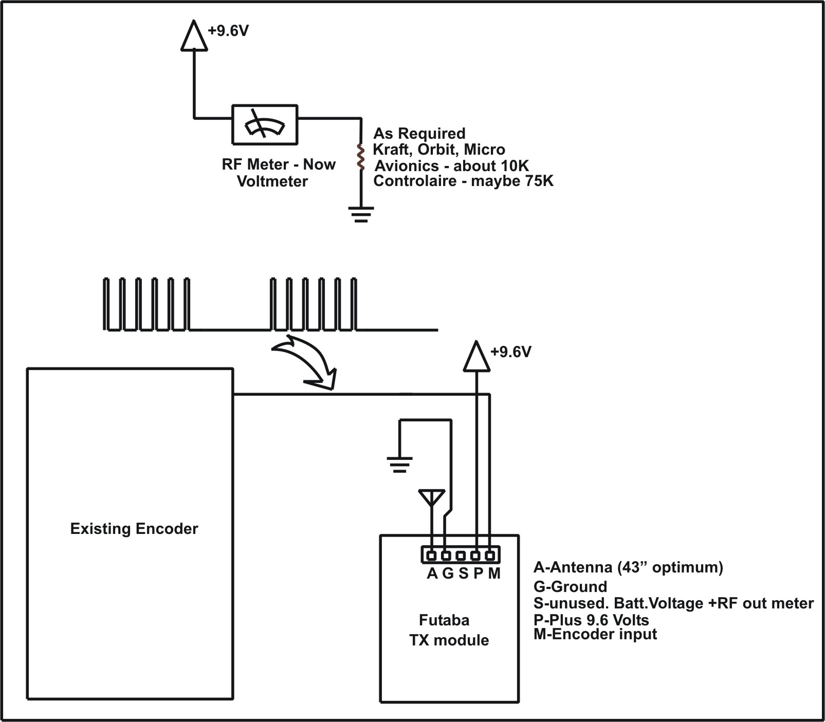
Here's a simplified block diagram of the conversion. The meter resistor
shown
is just what I found from experience. You may want to vary it a little
to get
the desired deflection.
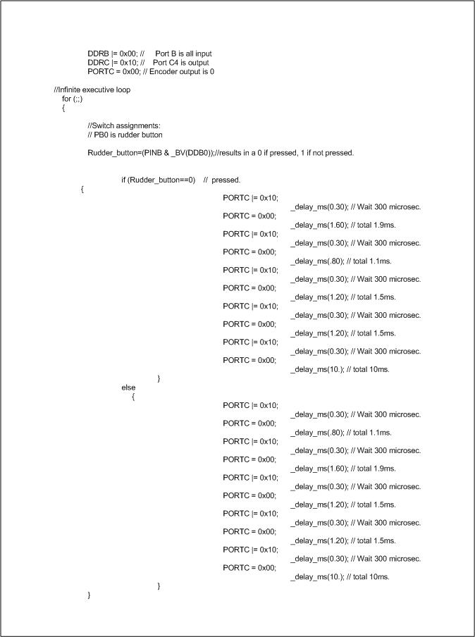
Once you've located a point on your encoder where you get the pulse
train
shown, you can begin to wire up the RF module. Your pulse train will
likely be
upside down, and you will have to invert it to get the signal shown.
The high
level may be from TTL to 9.6V....it's not too critical. You can
order part number 517-647-07-36 from Mouser
and cut it down for a nice connector to the module. It's not a bad idea
to add
a little bypassing right at the connector power leads, say 0.1MF.
FYI, the positive pulses are fixed at about 350ns, the time between
each rising
edge and the following one is the pulse width for each channel (try 1.0
to 2.0
ms. centered at 1.5ms.) and the frame repeats at about 16ms.
The TK module is the more powerful Futaba module, but I've used the
other one
successfully, too.
A word about legalities. I'm told that you can't do this with a 72MHz
module as
they were type accepted in the Futaba cases only. This conversion
is shown
for ham band operation only. Once you have wired everything up, get
access
to a spectrum analyser and make sure the power output looks good and
the
harmonics and sidebands are 60dB or more down! I've received brand new
modules
that don't make spec, so don't skip this step!
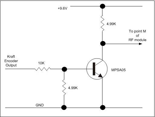
Circuit Details for Kraft:
Kraft Gold Metal and early seventies transmitters are easy to obtain on the used market as so many were sold. They were a bit pricey at the time, $400 for a four channel when the Japanese products were beginning to appear for half that. But time has shown that they are mechanically sturdy and generally outlast their contemporaries. There is no reason that a well-kept Kraft might not be flying in the next century if our hobby exists then. If you run across a PCS, get it! The circuitry is pretty much identical and it is great fun to show up at the field with a chocolate colored transmitter. My point here is that I am offering more detail on these particular transmitters because your chances of success (and satisfaction) are highest with them, IMHO.
The Kraft encoder (like most of the era) consists of a master clock that kicks off a chain of one-shots. The timing of each one-shot is controlled by a fixed capacitor and variable resistance, the latter being a mix of control pot, alignment pot and possibly trim pot. Each one-shot has an output that is high until it is fired and then it goes low for the RC period. The outputs are all ANDed together by tying them to the cathodes of diodes that have a common anode. At that point, the pulse train is complete, but fed into the circuit shown below for some final shaping.
Your first task in the conversion is to make sure the common diode point is connected to the 1K as shown. You may have a buddy-box circuit connected at this point with a .05 capacitor in series with the 1K. You can bypass all that junk by removing the capacitor and connecting the 1K directly to the diode AND. Note: You have the option of skipping this step and leaving the buddy box circuit intact.
Next, get rid of the RF chain. It's the circuitry not shown to the right of the first diagram below. At the very least, remove the crystal, the nearby transistor, variable coils and/or variable capacitors and any transistor with a heat sink. Generally speaking Kraft tends to demark the RF section in a literal "strip" that is easy to identify. I usually work my way down the strip shearing off components with a pair of dykes. The big trimcaps are best unsoldered.
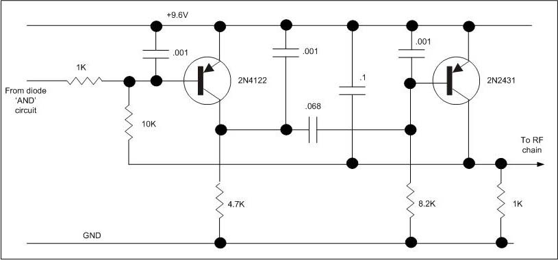
At this point, the circuit board should be cleared of everything but encoder. If you wish, you may cable up your power, turn it on, and scope a few points of interest. You will find that the output of the shaping circuit above is inverted to what a Futaba module wants. I have provided a circuit below that will solve this problem. You should have little challenge finding a clear spot on the board to construct this inverter circuit. If desired, you may put it on a separate postage-stamp-sized board elsewhere in the transmitter. The point in the first diagram titled "to RF chain" connects to "Kraft Encoder Output" in the second diagram. Resistor values in the circuit are probably not that critical, so feel free to try what's in your junkbox, but you may want to keep the ratio of the two base resistors close to that shown. I like MPS-A05s a lot so that's what I show here, but any garden-variety NPN should work fine.
Other Notes:
Keep the antenna wire as short as possible, say 2-3" from the module to antenna base.
Make sure the encoder board and module have good case grounds.
I like to epoxy a 100K multi-turn trimpot to the side of the meter and place it in series with the 9.6V bus (see block diagram). Adjust as required.
Kraft single-stick transmitters have a black wire coming from the rudder pot that attaches to the common +9.6V bus that runs to all the other control pots via red wires. Weird, huh?
Note: I have documentation for some old RC equipment as listed below. Email me if you would like a
copy. Also, if you have any documentation for other RC equipment
(particularly
pre-1970) , I'd appreciate a copy!
Note #2: Response to my documentation CD has been great. My friends have supplied me with many additional files for antique RC equipment, so the list continues to grow.
Note #3: Most all of my documentation has now been shared with Tom Mavracic and may be found online at vintagercfiles.com
Documentation
available:
Ace
....Digital 1-8 receiver complete manual.
....Half-A 2 channel receiver schematic.
....Bantam Midget servo complete manual.
....Silver Seven Transmitter schematic w/narrowband mods.
Annco
....Multi servo instruction sheet
Babcock
Bonner
....Transmite schematic with suggested modifications
....Transmite instruction sheet
C&S
....Cardinal receiver schematic.
....Pulser instruction sheet w/schematic and suggested modifications
CG
Citizen-Ship
....3VTR receiver instruction sheet
....Actuator instruction sheet
Controlaire
ED
EK Logictrol
Fly-tronics Engineering
....FAIL-SAFE various hookup drawings
F&M
....Midas reed receiver power and servo wiring
....Digital 5 manual w/schematics
....Matador Warranty
Glass City
Graupner
....Unimatic instruction sheet
Grundig
....Transmitter schematic.
Heathkit
....GDA 1205-5 servo schematic
Hitec
Hobby Specialties
....GM Nicad instruction sheet
....GM Geni servo instruction sheet
Kinematic
Klinetronics
Kraft
....KP-5 Sport Series complete service manual.
....Gold Medal Series complete service manual
Metz
Micro Avionics
Min-X
Orbit
....4,6,8,or 10 Channel relay receiver schematic (tube).
....10 receiver schematic (all transistor).
....10 simultaneous tone transmitter schematic (all tube).
....2-10 relayless receiver schematic.
....4 channel transmitter (all tube).
....10 channel transistorized manual w/schematics & hookup
OS,Controlaire,World
....SH100 to OS S103 Single servo hookup
....World S11,S12,S16,S17 servo schematics.
....World Mk4,Mk5 Rx & Tx schematics.
OS
Otarion
Pro-Line
Rand
RCS
....Competition 10 receiver schematic.
RCM
....Article "Lil Bandit" homebrew reed transmitter.
Royal
Sampey
Space Control
VictoryInd
If you think this kind of stuff is cool, check out this great Japanese museum!
Here's another link to a Japanese site with a lot of nice photos.
But the very best one is HERE