Grotto 2: Pull Pull Control Rigging
This page designed to operate under Netscape Navigator(TM) Version
3.0
Last update 02FEB2019
Pull-Pull Control Rigging
By Ron Ellis
My past several planes have used pull-pull on at least one control surface and my pattern planes have become almost exclusively pull-pull on the empennage controls.
Occasionally, I have had cable slack problems on the “release” side of the system, but this has always been explainable by the pivot point of the control surface’s horn not being lined up with the hinge line. Since the “horn” I like to use on pattern planes is basically a 6-32 bolt with an MK ball-bearing clevis assembly at the top, I can rectify these problems by just bending the bolt as required.
In the past, I have relied on the ol’ eyeball in making these adjustments with great success. My latest plane, however, was not so easy and required that I learn more about pull-pull to solve this problem. Hopefully this article will pass on the results.
Tension:
Many pattern modelers set up their pull-pull arrangements with considerable tension. This is neither necessary nor desirable, in my opinion. Over-tensioning is often, I believe, a response of the modeler to the slackening problem. I have had several nice flying planes with excellent control surface resolution that have what appears to be dangerously low tension in their cables. But then, they also have not had slackening on the release side, either.
I wish someone manufactured an inexpensive tension gauge so I could properly relate to you the magnitude of tension I run on my cables. Suffice to say at this point that plucking my elevator cables results in a barely audible “thunk” and not a “ping” at all. Sort of like a #64 rubber band stretched to about…..but I’m getting ahead of myself here.
Perfection:
We all strive to do our best when we set up an aerobatic plane, but experience tells me that perfectly matched tension on both sides of a pull-pull system throughout it’s range is difficult to achieve (and probably not necessary).
Still, allow enough time to do your setup. There’s a lot of checking and re-checking required to get good results. A couple of hours spent here may pay off in flight performance later.
Typical system:
For cables, I usually use plastic-coated steel leader from Wal-Mart. I use about 60 pound test. If you decide to go this route, don’t forget to grab some of the appropriately sized crimps while you’re there.
Kevlar works well also, is lighter and non-conductive. It also picks up CA nicely. Kevlar frays, however, so you must add plastic tubing to your exit slots.
For servo arms, you can buy second-source metal arms or, if you use Futaba servos, modify the giant plastic wheel that comes with them. The modification is to cut the wheel into a “D” with the flat side just touching the molding that fits on the servo output shaft. This wheel is about the minimum size I would use on a 2-meter pattern plane.
Mount the servo so it’s output shaft is in the same axis as the control surface’s hinge line. My rudder servo usually ends upright in the top rear of the radio compartment while the elevator servo is on it’s side and mounted on the bottom of the radio compartment slightly ahead of the rudder servo.
On the servo end, I loop the cable though the outermost holes of the arm and crimp. I usually end up with the crimp being about an inch away from the arm, but this exact distance is not critical. Later, when the system is all set up, I like to put a drop of CA inside the crimps.
On the control surface end, I use a Dubro 4-40 rigging coupler (DUB618) threaded into a 2.5mm MK Ball bearing control horn clevis (MKD0892). I tap the ball bearing part to 6-32 so it will thread over the bolt in the control surface. Loop the cable through the Dubro coupler and crimp the same as you did on the servo end. I like to set up the controls as closely as possible before committing to the crimp-and-CA step. Even so, always be prepared to re-rig a cable. You did buy an extra spool of leader when you were at Wal-Mart, right?
I use a single servo for both elevator sides. The redundancy of dual servos is comforting, but getting them to track together is a serious issue. Choose your poison. I like to use a single cable that pulls both of the elevator tops and a single cable that pulls both of the elevator bottoms. This avoids a crimping mess at the servo end.
The elevator rigging procedure then ends up like this: Attach cable to bottom elevator horn, feed cable through fuselage slot, feed through crimp at servo, servo wheel, back through crimp, out fuselage slot and attach to bottom elevator horn. Repeat for top of elevator horn. The trickiest part is feeding the cable out of the fuselage slots. It’s really not that hard if you have a piece of music wire with a small hook bent into one end. My last plane had plastic tubing instead of just slots for fuselage exits and that resulted in an interesting procedure involving a steel rod, rubber band, Mag-light and TV camera…perhaps a subject for another article.
Special tools required for setup:
1. Servo driver with digital display
I have an old Ace unit that has served me well for years. You can get one
from any of the following sources:
Radio South
http://www.radiosouthrc.com/pro-servo_master.htm
Vexa
http://www.vexacontrol.com/
GWS
http://www.gws.com.tw/english/product/servotester/servo%20tester.htm
You could possibly use your radio for this as long as you can guarantee
that you are able to repeatedly return to the same two positions spaced
equally from center. If you have a way to digitally display the actual pulse
width going to your servo, then that will do. You want the display in order
to record your results and assure consistency.
2. Ivan’s Magic Gadget
The IMG hasn’t been produced by Gator for some years, but you can make your
own with replacement parts available in Coreldraw files on my web site (
http://www.mindbend.site/rcpattrn/rcpattrn.htm
). Another good one is the LASER Measurement System from Budd (
http://www.buddengineering.com
). I don’t recommend some of the other ones because either they don’t read
out in degrees, or they don’t have accuracy exceeding one degree, which is
what you need.
3. Rubber bands. Two each clean and fresh, please. There
may a substitute item, but I found these handy.
Theory:
Faced with the daunting task of making servo arm, four cable ends and two control surfaces all move smoothly in unison, I did what any modeler would do: I screwed around with it for a couple of nights and then gave up.
As you may have guessed by now, describing the problem helped form a solution. To perform the setup, we will separate the problem into four pieces and solve them individually. We will make the servo pull on only one cable end at a time, leaving the other three disconnected. Resistive tension will be provided by the rubber bands. The servo will be commanded to displace it’s arm an equal angle either side of neutral while we measure the deflection of the control surface. We will then adjust (bend) the control arm as required to achieve equal control surface deflection.
Procedure (elevator example):
1. Plug your servo into your servo driver and adjust
your servo driver output to 1.50ms. pulse width. (If your nominal servo center
pulse width is different, then use that value, but I will continue to use
1.50 here as an example.)
2. Install the control arm onto the servo in a position
on the output shaft that is as near vertical as possible. You may not be able
to get it perfect because of the splines of the output shaft. Now adjust
the servo driver to trim the arm to a position as near vertical as possible.
Record this pulse width value as we will be returning to it many times. In
our example, let’s suppose it’s 1.47ms.
3. Disconnect three control surface horns from their cables.
This is done by just removing the appropriate clevises. One cable should
remain connected to it’s control horn. That’s the one you’ll be operating
on.
4. Apply bias to the opposite side of the control surface
using the rubber bands. Here’s a way you can do this: A)Tie two #64 rubber
bands together to double their length. B)If you are going to work on the
bottom left control horn, loop one end of the rubber band around the top
left control horn, pull it around the leading edge of the stab and
loop the other end around your tail wheel. C) If you are going to work on
the top left control horn, loop one end of the rubber band around the bottom
left control horn, pull it around the leading edge of the stab and
loop the other end around your rudder horn. I’m sure someone can think of
a nicer way to do this, but it worked for me and didn’t require that I make
anything.
5. Adjust the clevis to center your surface. I aligned the
end of my elevator with the inside of the stab tip.
6. Set up your IMG. Be careful here! The 5” distance from
the hinge line to the meter arc is important and measurements have to be
accurately repeated. Set to zero degrees.
7. Use the servo driver to determine your maximum control
surface throw. The exact value is not that important. When the measurements
become critical, you want to be sure the surface does not risk hitting it’s
limit. Let’s suppose that in our example the limit is about 22 degrees up
and down. You would like to do your measurements around 75% of that, maybe
15 degrees or so.
8. Determine a good pulse width measurement range that
gives the setup range desired. Let’s suppose that we find that 14 degrees
deflection in one direction is the result of a 1.77ms. pulse, exactly .30ms.
away from our 1.47ms. center. Since that’s easy to remember, from now on
we will attempt to adjust centering at 1.47ms. and equal deflections
at 1.17 and 1.77ms.
9. Measure the degrees deflection in both directions (1.17
and 1.77ms. in our example)and adjust the horn as required. If you need more
throw when the cable pulls, bend the horn toward the front of the plane.
If you need more throw when the cable relaxes, bend the horn toward the rear
of the plane. For each horn bend you will have to adjust the clevis to re-neutralize
the surface.
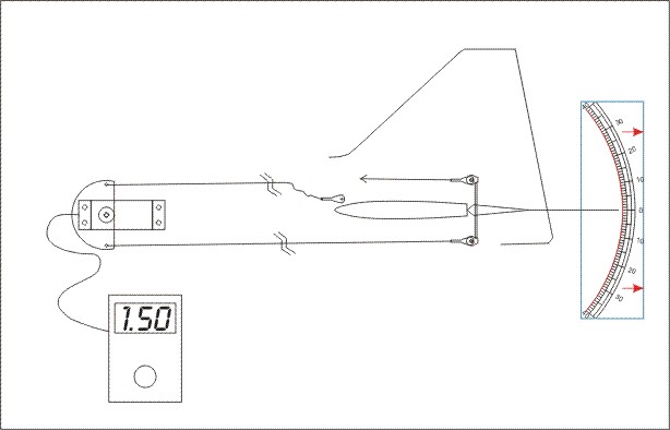 Figure 1: Here’s an example of how a setup might procede.
First, get everything as square as possible with the servo centered. In this
picture, the servo disk happens to be dead on with the nominal 1.50 ms. Pulse
input. The Magic Gadget is set to display zero degrees. Note that the arrow
pulling the top of the control horn represents the tension of a rubber band.
Figure 1: Here’s an example of how a setup might procede.
First, get everything as square as possible with the servo centered. In this
picture, the servo disk happens to be dead on with the nominal 1.50 ms. Pulse
input. The Magic Gadget is set to display zero degrees. Note that the arrow
pulling the top of the control horn represents the tension of a rubber band.
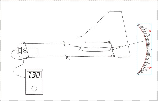 Figure 2: Now we displace the servo with a 1.30 ms.
Pulse input. We note that the Magic Gadget displays +14 degrees.
Figure 2: Now we displace the servo with a 1.30 ms.
Pulse input. We note that the Magic Gadget displays +14 degrees.
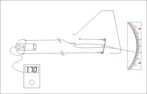 Figure 3: Oops! Moving .20 ms. in the other direction
to 1.70 ms. results in a control surface deflection of only 11 degrees.
To increase this we need to bend the bottom horn forward, re-center with
the clevis and measure again.
Figure 3: Oops! Moving .20 ms. in the other direction
to 1.70 ms. results in a control surface deflection of only 11 degrees.
To increase this we need to bend the bottom horn forward, re-center with
the clevis and measure again.
10. Repeat #9 for each of the next three horns completing
first one side and then the other. Set for equal deflections to the degree
value you got in the first setting. You may be required in some cases to wind
the ball bearing horn toward the top of the bolt to decrease total throw
or toward the bottom of the bolt to increase total throw.
11. Once all the throws and centers have been matched, you
should be able to set aside the rubber bands, connect up all the clevises
and have perfect tracking with no sagging cables. If this is not so, or you
have any binding, repeat the procedure until you are satisfied. Cable tension
should be on average close to that of the rubber bands and quite adequate.
Synopsis:
Drive your servo from a source that can repeatedly produce the center pulse width and two pulse widths equidistant from center. Let the servo drive only one side of the horn at a time and tension the other side with an elastic band. Adjust the horn as required to achieve equal control surface deflection in each direction when the servo is driven with corresponding pulse width variance. Work at somewhat less than full control surface deflections to allow some adjustment overhead.
Reference:
Interference or Pushrod-it is? Sawyer
RCM May 1966