The Great Rudder Experiment
By Ron Ellis with Mike Whaley
Like many others, I've observed that as our planes have gotten bigger, rudder servo torque requirements have also increased. While other control surfaces have not changed in their requirements since the .60 two- stroke days that much, most pattern planes sport $100 servos to swing that rudder. Pattern fliers have thus empirically proven that these bigger servos are necessary.
Now, I like electronics as much as the next guy (maybe more so), but the purist in me says that something is amiss here if we have to go to such extremes. I like getting a plane as aerodynamically perfect as possible before touching the mixers, fr'instance. It is certain that if a modern pattern plane had to be manned, the pilot would have to have pretty muscular legs to handle the yaw axis.
Many full size planes, and some larger aerobatic models have began to sport deflective rudder area ahead of the hinge line. This is an old technique for de-loading the surface. (Another is the servo tab.) We know that this works, but how much surface needs to be ahead of the hinge line? I looked in a couple of aerodynamics books for the answer and found no information on surfaces deflected at 45 degrees, a value we commonly use.
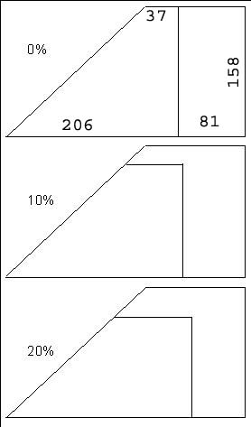
So I enlisted the aid of Mike Whaley, fellow IRKS club member and techno-geek. Mike suggested an experimental setup mounted on a moving vehicle to get some actual force numbers and I thought it was a great idea. Sam Turner supplied the outline for a Saturn rudder and fin we could use as a point of reference. I began to cut wood, designing the experiment as I went. I wanted to make at least three fin/rudder combinations and settled on a stock Saturn (0% ahead of hinge line), 10% and 20% area ahead of the hinge line. I wanted the actual deflected area to remain the same to simplify the comparison of the three setups. The result of this was that area was added to the moveable portion at the top of the rudder and subtracted from the top of the fixed portion. The hinge line would then move to the rear to compensate, adding back the lost area to the immovable portion. To simplify, the fin/rudder would be a flat plate approximation having no real airfoil, just rounded corners. Here's a picture of the layout of the three test units:
The fins were mounted to a plywood plate in a holder system that allowed for a quick field change without affecting the control system. The rudder plate in turn mounted to the topper of my pickup with a vertical ply plate that slipped down between the cab and topper for access thru the rear cab sliding window, and stabilized with bungee cords on the rear corners of the baseplate. The controls were steel pull-pull cables, mounted to the rudder at the hingeline with the cables attached 3.5 inches out from the rudder. The cables were run in a standard fashion over small pulleys into the cab and to a small digital fish scale. The mass of the fish scale was counterbalanced with lead shot on the opposite cable. The vertical plate had graduated markings on it for 0, 15, 30 and 45 degrees.
A test run with the 0% unit took place in December with cassette tape streamers to check for turbulence. Mike hung out the window of the truck and observed the airflow, which did indeed have some problems including very turbulent flow along the bottom of the plate. At Mike's suggestion I built a boundary layer diverter onto the front of the rudder plate to smooth out the airflow. This was a square ply plate with a wedge shaped piece of wood underneath…you may have noticed similar plates next to the jet intake of some fighter planes like the F-4 and F-15. We also had a problem with the fin/rudder wanting to bend in the roll axis, so some guy wires were added. Another effect noted was a strong leading-edge vortex on the side of the fin that is in the direction it is lifting, similar to any delta-wing planform. This was probably a side-effect of the flat-plate airfoil and was deemed to be unlikely to invalidate the results.
Finally, on the night of January 13 with the wind calm and the temperature near 70 degrees F., we decided to make a data run. First we repeated the airflow check to see if the boundary layer diverter was effective, and determined that it was a great improvement. We took data on the way out of Melbourne and down I-95 to Fellsmere and back with stops to change fins. Everything went well until we were about to take the last data point, 75mph with the 20% unit. We were in the middle of a pause to let a semi pass when we heard a sharp crack. We stopped immediately and found that the boundary layer diverter had evaporated into the night above the interstate. Oh, well. Fortunately, Mike thought he had a good preliminary reading of the data and we used that value…it appears to be right. We also took some data without the boundary layer diverter, but it is obviously pretty far off so we do not submit it here.
Results:
The data was gathered in terms of ounces of pull required to maintain a given deflection. Then it was converted to ounces and then divided by the moment arm (length) of each half of the rudder horn to arrive at the customary unit of ounce-inches of torque. Given that the maximum value we tested was around eight pounds of pull at 45 degrees deflection, it was a good thing we didn't use a 1-inch control horn like so many models have!
Here's a graph of our data using the stock fin/rudder. It clearly verifies
the impossibly high torque loads we are expecting our servos pull. Each
line represents data taken at a given velocity in increments of 10 mph
from 25 to 75 mph. A 3-1/2 inch control arm was used in the torque measurements
to reduce linkage slop. 
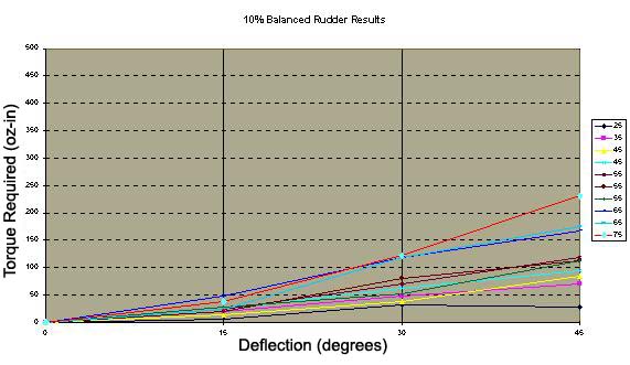
Here's the 10% balanced fin/rudder. The peak load at 45 degrees deflection
has been nearly cut in half compared to the stock unit.
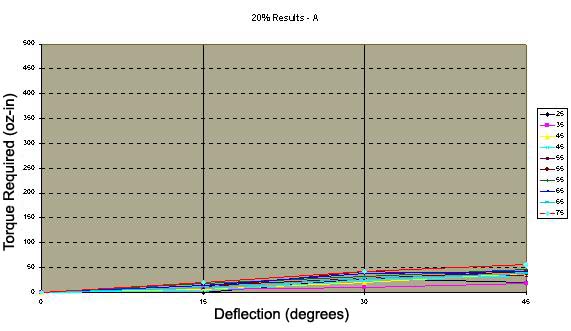
20% is better still! Things have started to flatten out here, and Mike
actually could feel the ease of operation. Now we're in the range of what
a standard servo can realistically handle.
The bottom line: Pattern plane designers should consider the use of counterbalanced
rudders in 2m sized aircraft. Existing servos cannot be expected to overcome
the aerodynamic loads at our rudder sizes and airspeeds. 20 to 25 percent
may be a good starting point for such balancing. Incidental evidence suggests
that the rudder operation is stable under these conditions and free of
flutter.
-Ron
FOLLOW UP EMAIL:
Subject: Rudder Balance Tabs Date: Fri, 12 Mar 1999 11:33:30 EST From: MAS36462@aol.com To: rellis2@mindspring.com
Hello Ron, I just loved your article. What fun you must have had with this project!
I am not intending to rain on your parade. I am not very qualified to even comment, but I have never let that deter me before!
If you must balance tab, do so other than at the top of the rudder! The reason the loads dropped is because the balanced area was stalled-not what you really want happening with the most effective section of your rudder on a pattern plane! Reason for the stall is that the AOA of the balanced section was double that of the non -balanced section! At 45 degrees deflection, only the balanced section is at 45 degrees AOA! Rest is 22 & 1/2 degrees or less.
My 2 cents worth is that you want to increase the efficiency of the rudder so that large deflections are not necessary (undesirable for many reasons!). Easiest way is to increase the "aerodynamic area" by "capping" the top of the Stab/rudder with a plate. This creates better airflow over the top of the rudder and the increase in drag is offset by the decrease in vorticies. (Vortex generators and strakes would also work but unless you use the wind tunnels at Embry Riddle you would be hard pressed to locate them accurately!) By the way, all that massive rudder area on the lower half of the rudder are flopping around in dead air most of the time and a waste of weight-strictly asthetics. Good place for "dynamic" counter balance WEIGHT to balnce the rudder. (this would help reduce loading and eliminate flutter).
Using a thicker airfoil number for the to of the stab/rudder near the top would increase efficiency. (it would not have to be physically thicker-just higher NACA #!)
Decreasing the chord near the base of the stab/rudder would increase efficiency(less sweep root to tip).
I mentioned Embry Riddle as I was there recently visiting and talking with some graduate students working in their aerdynamics labs. They have some great stuff and I bet a good resource for doing some testing.
Finally, a good way to reduce the load on the servo by 50% is to run the rudder pull pull from a bearing mounted swival that is driven by the servo outside the attach point of the cable to the rudder. I.E., the distance from the pivot point on the swival to the attach point of the cable on the swival is 'x' and the distance from the pivot point on the swival and the attach point of the servo is '2x'. Load is cut in half, sensitivity is cut in half (servo is moving twice as far as cable). Swival carries all the cable tension load.
The Olympic sailplanes (rudder & elevator only) had counter balanced rudders and turned like a dog until the counter balance was removed. Despite a 20 % reduction in rudder area the plane turned on a dime! My full house 3 meter sailplane has 50% of the fin area of a 2m pattern plane, yet will point roll and stall turn like a pattern plane using 30oz torque servo! Think about it. In F3B these sailplanes get up to 90 mph when they start their turns at the pylons! (Granted -not much rudder is used in the turns)
Just some food for thought
I'm not doing much flying and what I do is regular and electric sailplane. CDed at Nats last year and again this year in nostalgia sailplane. Compete in 2 meter, unlimited, & 3 channel sailplane as well as Electric A ,B, & Old Timer. More bang-less bucks! NO JUDGING!!! Stop watch and landing tape tell the storey! (Easier too!!!!)
Say hi to everyone for me. Mike McGowan
Subject: Re: Rudder Balance Tabs Date: Fri, 12 Mar 1999 15:12:15 -0500 From: Ron Ellis <rellis@harris.com> Reply-To: rellis2@mindspring.com To: MAS36462@aol.com, S1Turner@aol.com, rellis2@mindspring.com References: 1
Hi Mike- Good to hear from you; it's been a while.
Did you find a copy of the pictures of the rudder/fin and test curves? Bill didn't print them in the hardcopy article.
I must admit, I did this from a fairly stupid standpoint not being an AE. And besides, my parades always end up sopping wet!
I wonder if I could follow up your comments with some questions.
MAS36462@aol.com wrote:
> Hello Ron, > I just loved your article. What fun you must have had with this project! > > I am not intending to rain on your parade. I am not very qualified to even > comment, but I have never let that deter me before! > > If you must balance tab, do so other than at the top of the rudder! The > reason the loads dropped is because the balanced area was stalled-not what you > really want happening with the most effective section of your rudder on a > pattern plane! Reason for the stall is that the AOA of the balanced section > was double that of the non -balanced section! At 45 degrees deflection, only > the balanced section is at 45 degrees AOA! Rest is 22 & 1/2 degrees or less.
I'm afraid you lost me here. 1) what is AOA? 2)Is there some kind of rule-of-thumb here? The entire moveable area was deflected 45 degrees to the relative wind. I agree that it may be stalled. Do you mean that the area behind the fixed fin is not stalled? 3) Sam and I have been talking about hinging a rudder 25% behind it's leading edge-any comments?
> > > My 2 cents worth is that you want to increase the efficiency of the rudder so > that large deflections are not necessary (undesirable for many reasons!). > Easiest way is to increase the "aerodynamic area" by "capping" the top of the > Stab/rudder with a plate. This creates better airflow over the top of the > rudder and the increase in drag is offset by the decrease in vorticies. > (Vortex generators and strakes would also work but unless you use the wind > tunnels at Embry Riddle you would be hard pressed to locate them accurately!) > By the way, all that massive rudder area on the lower half of the rudder are > flopping around in dead air most of the time and a waste of weight-strictly > asthetics. Good place for "dynamic" counter balance WEIGHT to balnce the > rudder. (this would help reduce loading and eliminate flutter).
I recall the Deception had no moving rudder below the fuse line. I think the real reason for bringing the hinge line on down is to simplify tail-wheel and control setup. Conventional wisdom (which may not be very wise) about rudders these days suggests that the bigger, the better for low speed and 3D use. So what if it's not efficient at high speeds; you don't need the deflection there. We'd like to not hit the limits of servo power, though.
> > > Using a thicker airfoil number for the to of the stab/rudder near the top > would increase efficiency. (it would not have to be physically thicker-just > higher NACA #!) > > Decreasing the chord near the base of the stab/rudder would increase > efficiency(less sweep root to tip).
Decreasing the rudder chord near the base, you mean?
> > > I mentioned Embry Riddle as I was there recently visiting and talking with > some graduate students working in their aerdynamics labs. They have some > great stuff and I bet a good resource for doing some testing. > > Finally, a good way to reduce the load on the servo by 50% is to run the > rudder pull pull from a bearing mounted swival that is driven by the servo > outside the attach point of the cable to the rudder. I.E., the distance from > the pivot point on the swival to the attach point of the cable on the swival > is 'x' and the distance from the pivot point on the swival and the attach > point of the servo is '2x'. Load is cut in half, sensitivity is cut in half > (servo is moving twice as far as cable). Swival carries all the cable tension > load.
Yes, but again, you can't get the high deflections desired at very low (hovering or near-stall) speeds.
> > > The Olympic sailplanes (rudder & elevator only) had counter balanced rudders > and turned like a dog until the counter balance was removed. Despite a 20 % > reduction in rudder area the plane turned on a dime! My full house 3 meter > sailplane has 50% of the fin area of a 2m pattern plane, yet will point roll > and stall turn like a pattern plane using 30oz torque servo! Think about it. > In F3B these sailplanes get up to 90 mph when they start their turns at the > pylons! (Granted -not much rudder is used in the turns)
Is prop wash not a major factor?
Subject: AE? Date: Sat, 13 Mar 1999 23:13:57 EST From: MAS36462@aol.com To: rellis2@mindspring.com
1) Sorry, AOA=angle of attack. Angle of attack is defined as the angle between the relative wind and the line created by drawing a straight line from the trailing edge to the leadind edge of an airfoil. If a vertical stabilizer is hinged with a straight vertical line then the AOA is determined by an imaginary line from the trailing edge of the rudder to the leading edge of the vertical stabilizer. (as viewed from above). A rudder that has an extension forward of the hinge line 'breaks' that imaginary line and the portion of the rudder that extends forward of the hinge line is now an airfoil with an AOA defined by the line from the trailing edge of the rudder to the leading edge of the rudder!
An AE would give you all the proper language and reasons, but my understanding is that once a control surface 'stalls' the pressure differencial forces commonly reverse (especially on the rudder-ala-a few B-737 crashes!!)
So, draw a wing cross section with the traditional aileron deflected. The AOA is the dashed line you would draw from the trailing edge of the aileron to the leading edge of the wing. Now superimpose the same cross section with a "balance tab" forward of the hinge line. The AOA of that aileron section is now defined as the dashed line from the trailing edge of the aileron through the leading edge of the aileron!
What I didn't mention was a term, 'critical AOA (the angle of attack at which a surface stalls)' Trust me, at well before 45 degrees AOA either a low speed or high speed stall occurs!
All that rudder mass area near the horizontal stab section is an attempt to get some deflection forces from that 'dead' air created by the intersection of the vertical stab and horizontal stab. But as you astutly (sp?) figured it is mostly there to hold the tail wheel! BUT, GET A HOLD OF NAT PENTON AND HIS FLASH GORDON SPECIAL-A TRUELY UNDERAPPRECIATED DESIGN- AND a lower fin of proper proportion with a lower rudder would help balance a certain amount of 'rolling' force from the 'upper' rudder.
Prop wash is a factor for short coupled aircraft is a problem but the beauty of the current longer tail moments of the 2m aircraft reduces that problem. Far greater problem is programming rudder mix with 4 cycle torque!!!
Excuse me, I got out of sequence with your questions. For every situation I can't equate, but yes the area behind the fixed fin is at a lower AOA and will stall later than that section that is "balanced"
Am not sure where your 25% is measured, but if you mean a narrow rudder but taller then you are on the right track! (Again, if you make a dorsal fin with a short chord and proportional sub-rudder clear of the fuselage it would also help)
Skip Deception paragraph for now
Decreasing rudder chord near base?--Yes and no!. Point is to reduce the sweep of the vertical stab!!! Reduce its chord so that the airflow will be more parallel to the fuse and less from the root to the tip of the vertical stab! See,.. that long chord creates seperation prior to the hinge line of the rudder near the base of the fin so most of the rudder is not helping the (here I got with theroms-airflow speeds and differential pressures which mean differential forces which mean "pushing the tail")yaw you want to create! [this is where it gets hairy, if you could 'trip' or turbulate the air it would delay seperation and the control surface would be effective, ala vortex generators or strakes] I mentioned the easy solution of the "cap" because that is what most manufactures of full scale aircraft resort to!
Ron, I enjoy the banter, the complex questions and the innovation, I think though that innovation gets penalized in the pattern community to a certain extent when it comes to "presentation". Your Satellite (sp?) was an example of what I mean. You lost points because it looked different and was hard to "read" by some judges. They didn't appreciate the aerodynamics because they were wrapped up in asthetics. But frankly, I lost interest in pattern when Nat Penton put up a rare flawless flight and got hammered by low life excuses for judges. His airplane was too radical for them, I guess, but by God, that one day and one time, I had the thrill of a life time watching those manuvers flown almost flawlessly. I was enlightened right then to a great realization of freedom of restricted imagination. I should have jumped up and cheered-my 9s & 10s were balanced by 6s & 7s!!! To this day, I regret not paying proper respect to not only a fine designer but to a fine person.
Damn, got my soapbox again! Hope I covered most of what you asked but not all because it is a thrill to hear from you!
Mike
Subject: Rudder stuff Date: Sun, 14 Mar 1999 01:15:11 EST From: S1turner@aol.com To: rellis2@mindspring.com
Ron, I read the exchange with Mike...Though it was pretty hard to follow, I think he's only partially correct... The bit about the AOA's makes sense. When the tip is aerodynamically counterbalanced, the tip's LE can be at an actual 45-deg, while the rest of the rudder is only about 1/2 that angle since it's hinged in the center and the effective AOA is determined by the line drawn from the LE of the FIN to the TE of the RUDDER. In the hinge-counterbalanced method that you and I were discussing, a different thing is gonna happen. As soon as the rudder's LE deflects into the slipstream, then we effectively a totally new control surface attached to the aft of the fin, and it will have the full AOA that the rudder-tip counter balance had...thus the rudder will be much more effective...maybe too much so at small deflections.
Sam
About the airfoil data, no data because the data stops at critical AOA. Soartech is a great resource of airfoil data
Flaw is that all airfoil data is based on a single airfoil across the span- something you can't really achieve on a vertical stab!
Please note that the stab shape can be physically thicker at the root than the tip, yet aerodynamically thinner!!!! I suggest that you try to approximate a NACA 0010 at the root and a 0014 at the tip. (try a 10 inch root chord and a 4 inch tip chord) Cut a couple of templates then cut out the stab/rudder in one piece (like a wing panel) This shape will have a physically thin tip but is "thickened" aerodynamically!
Now start with a one inch wide rudder full span. Mount horizontally with fishscales set to measure "lift" and use a low speed fan blowing through a wine bottle box (for uniform flow). See what happens to the "lift" as you increase deflection! I bet it will give a curve that will peak well before 45 degrees deflection! (I do something very similar to this with my Adopt-a- school class and it will "draw" a great L/D (lift over drag as AOA varies) curve! I suspend an airfoil with a pointed stick through it spanwise at the approximate high point. Supported above by a swivel then paper under pointed end and turn on the fan. Rotate swivel for changing AOA! Airfoil will go "UP" (i.e. horizontally in direction of lift force) and "BACK" (drag force). Plot the tip directly on the paper. Peak lift occurs usually around 25 degrees AOA for a fixed speed.
Remember that (shape dependent) the AOA increases for a given deflection as you progress from the root to the tip. There is another way to delay the spanwise airflow. You shape the crosssection so that the high point (thickest point of the airfoil) is an elliptical path, (for wings this is what the Shulman platform duplicates. the shulman platform is easier to build than a Spitfire wing!) The shape of the leading edge is not as critical as the shape of the high point! What this creates is a sweep of the low pressure point aft as you progress towards the top (tip), thus delaying the airflow movement spanwise (again a tip plate would be simpler and have more benefits.
I am glad you are addressing the empennage as it has really been ignored in most designs. Much smaller tail surfaces than what are being used today would work better. (More efficient, less drag, less energy needed for control) The proportions people are using are based on much shorter coupling (moment arms) than what at present on the 2m sq. Long tail moment is good. Smaller stabs would be good, too! Making a vertical stab similar to the horizontal stab would be great! (i.e. top area nearly equal to below horizontal stab area- don't count that "dead" area near the junction of the stabs.
Damn! I getting interested again!
Erin Go Braugh!
Mike
Subject: Date: Wed, 19 Jan 2000 00:22:56 -0500 From: Matt Kebabjian <mtk@Tensolite.com> To: "'rellis2@mindspring.com'" <rellis2@mindspring.com>
Hey Ron... I stumbled onto your page through other's pages and got into your experiment and Mike's comments. I believe he makes several key points regarding high deflections. However, at lower deflections, I'm not so sure that the arguments hold as well because the "balanced" segments would still be flying. Actually, even at higher deflections, if you disregarded that portion of the rudder area that was stalled, according to your empirical data, it should have taken more torque to move the remaining effective area than it did.
By the way, I believe I understand what you and Sam may do with the hinge line behind the rudder leading edge. If you are thinking about about exposing the rudder leading edge to the slip stream and opening a gap at the fin te, be very careful on the amount of rudder deflection you use: more than about 20 deg and you'll stall the whole control surface. The fin will be the only portion providing directional stability and may or may not be enough. The way Nat would explain it I think is that as any control surface is deflected on a conventional set-up, the airfoil is changed accordingly, providing lift in the direction opposite the deflection. The hinge gap is most effective at our speeds when it's air tight. By the way, at much higher speeds, as in commercial jets, the laminar sublayer of air is very well established and requires less tightness to make a surface equally as effective. At least that's how I understand fluid dynamics although I'm no expert, please. That's why extended surfaces work on a jet wing, even though you can see the ground through the gap.
Mike's right on the money with reduced stabilization areas; properly designed stabilizers in the tails of our long moment planes would require less contol surface areas and/or movement for equal action. But the torque required on the servos would be greatly reduced. That's precisely what Nat preached for years and I was a very willing pupil. The catch is, particularly with the horizontal stab, that that the tail volume coefficient( fancy term for essentially a calculation of the tail moment and area at the tail and I used to actually calculate it for various designs I made over the years, but haven't done it in years) should be larger than about .6 for our purposes. I think that present models have TVC's possibly over 1. It means they are extremely stable in pitch requiring very large elevators to make tha model do anything. Same holds true for the fin/rudder but since it's not as dangerous to the model little attention has been paid there. Too much stability in pitch makes an excellent trainer though. Hanno and Hans Prettner's models typically had TVC's in the .7-.77 area as had the early Matt designs. I never did calculate their vertical TVC's though, but I'd bet they did and they were quite low.
Nat's Express had a very low TVC both horizontally and vertically, for a pattern plane. I think he'd said it was in the .55-.6 area, but my memory isn't what it used to be and it's been about 10 years. You may recall the area of his control surfaces back there: pretty small. Nat's exquisite construction was so light that snaps and other violent maneuvers were a, well, a snap if you pardon the pun. I believe we could all do ourselves a big favor and start reducing the tail feathers considerably: for example the stab should be less than 20% of the wing and the elevators at most 30% of that. Less loaded performance and lighter to boot. Actually our model would fly with as little as 10% but wouldn't groove well .
Matt